


- Seamless integration between surface modeling and solid modeling.
Overview of the 3D CAD/CAM/CAE Solution System for Design, Simulation, and Manufacturing – CADmeister – Part 2
In Part 1, we provided an overall introduction to the CADmeister software. In Part 2, let’s take a closer look at the modules offered by CADmeister and how they can support your business in production planning.
Table of Contents
1. CAD 2D & 3D
1.1 BASE/ADVANCE Module (Modeling Design Tools)

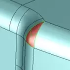
A wide range of fillet functions, including:
- Fillet
- Graded Fillet
- Automatic Filleting
- Collective Filleting
- Filleting at Junction Points

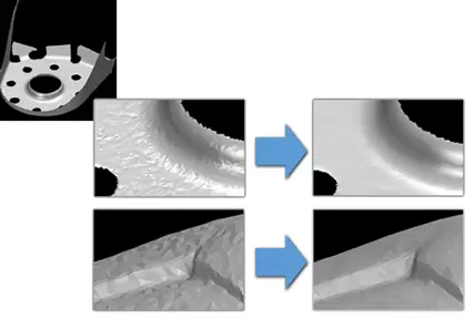
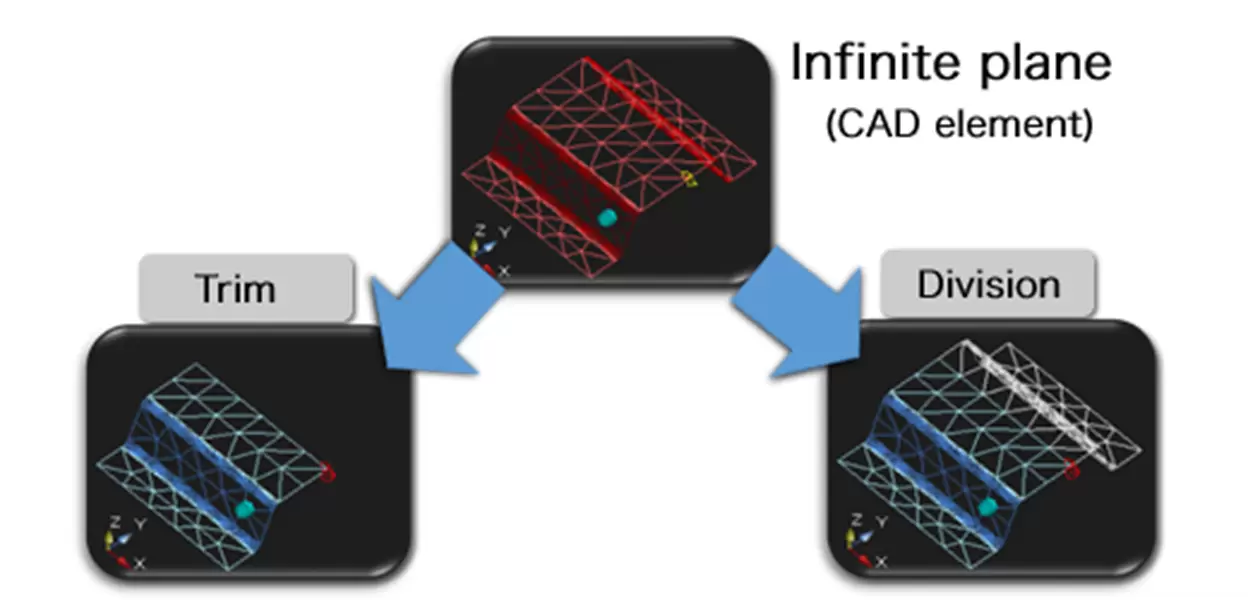
1.2 STL-EDIT Module (STL Data Editing Tools)
STL-EDIT is a tool that allows the use of STL data imported into the CAD system via 3D coordinate measuring tools. It is an essential tool for editing STL data.
Simplification
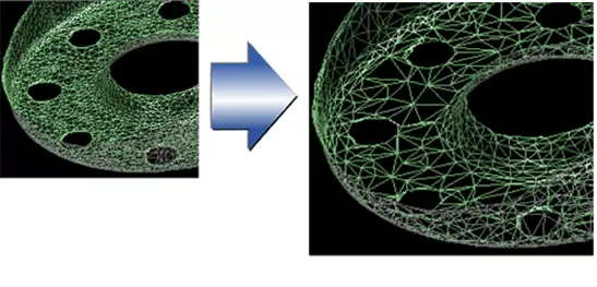
Noise Reduction
Smoothing
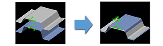
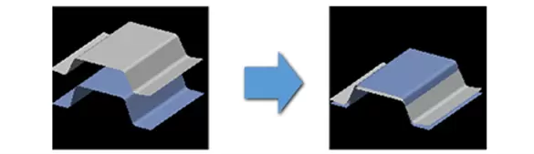
Trim
Position Alignment
Three-point method
Automatic
Manual
Extension
1.3 DATA EXCHANGE ModuleCADmeister supports the exchange of both standard and optional data formats:
- Standard data: Import/Export file formats including IGES, JAMA, DXF/DWG, CADCEUS, and STL. Export formats include XVL, VRML, and SVLX.
(These are default functions and do not require an additional license.) - Optional data: Import/Export file formats such as STEP, CATIA V4, CATIA V5, PARASOLID, I-DEAS, Creo Parametric, TDEX, JT, and TOGO. Export formats include NCVIEW and CAM-TOOL.

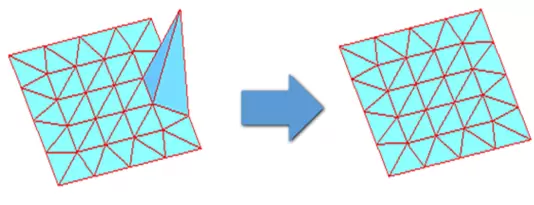
1.4 Mođun FILLET-REMOVAL SP 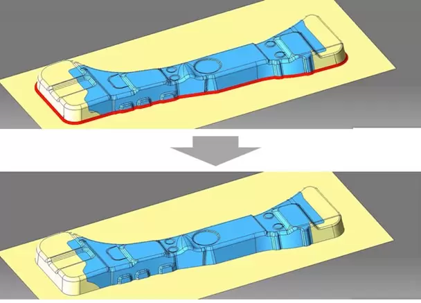
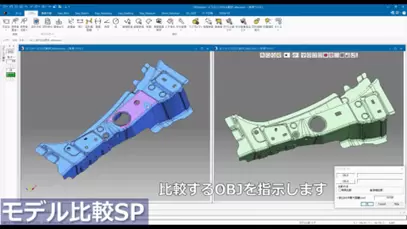
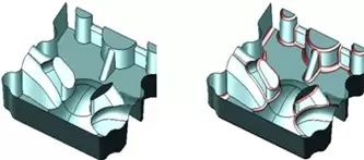
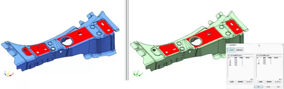
Mođun MODEL-COMPARISON SP
This function compares detailed 3D product models before and after design changes, displaying the changes both in a list and within the software interface. Specifically:
2. PRESS DIE
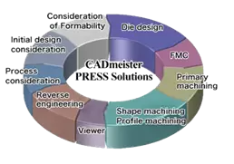
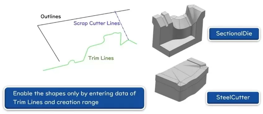
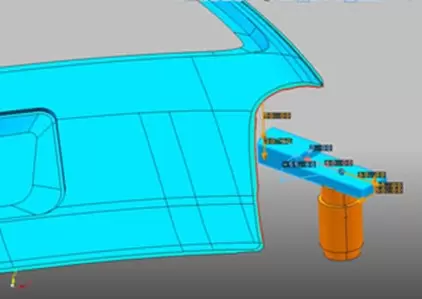
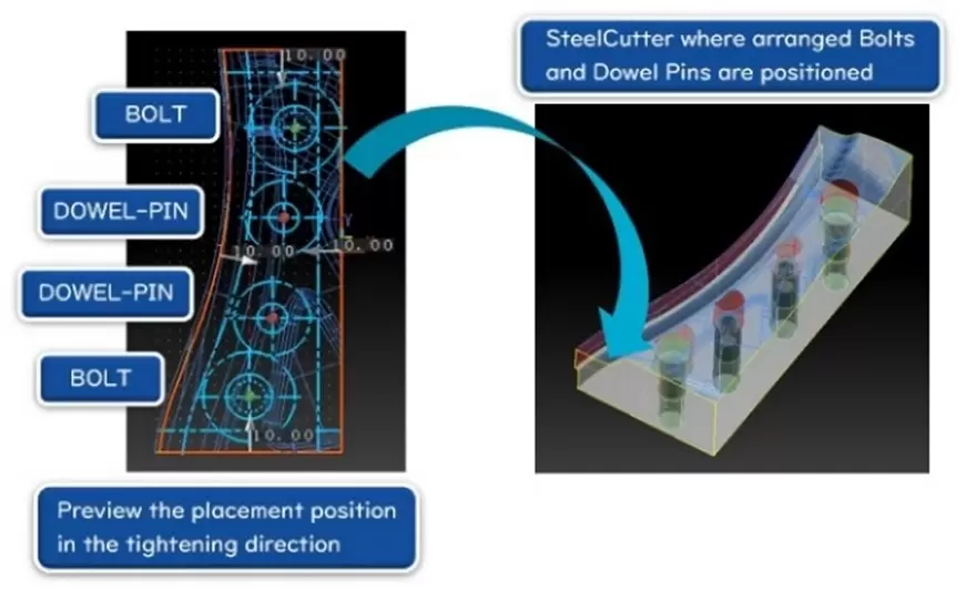
2.1 Mođun PRESS
CreateSectionalDies and CreateSteelEdges
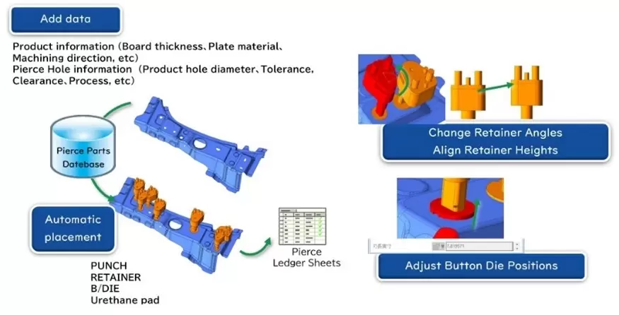
CashHole
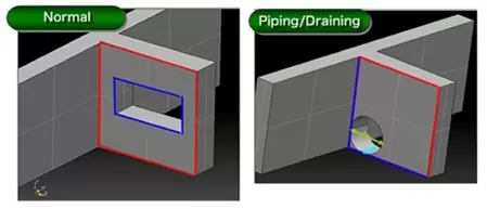
ShapeCreation
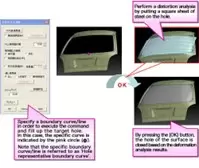
2.2 Mođun FORM-EX
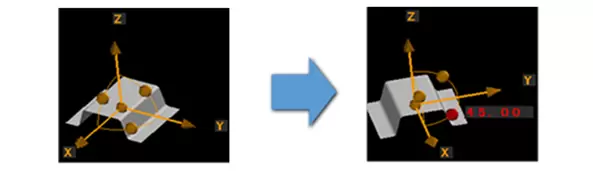
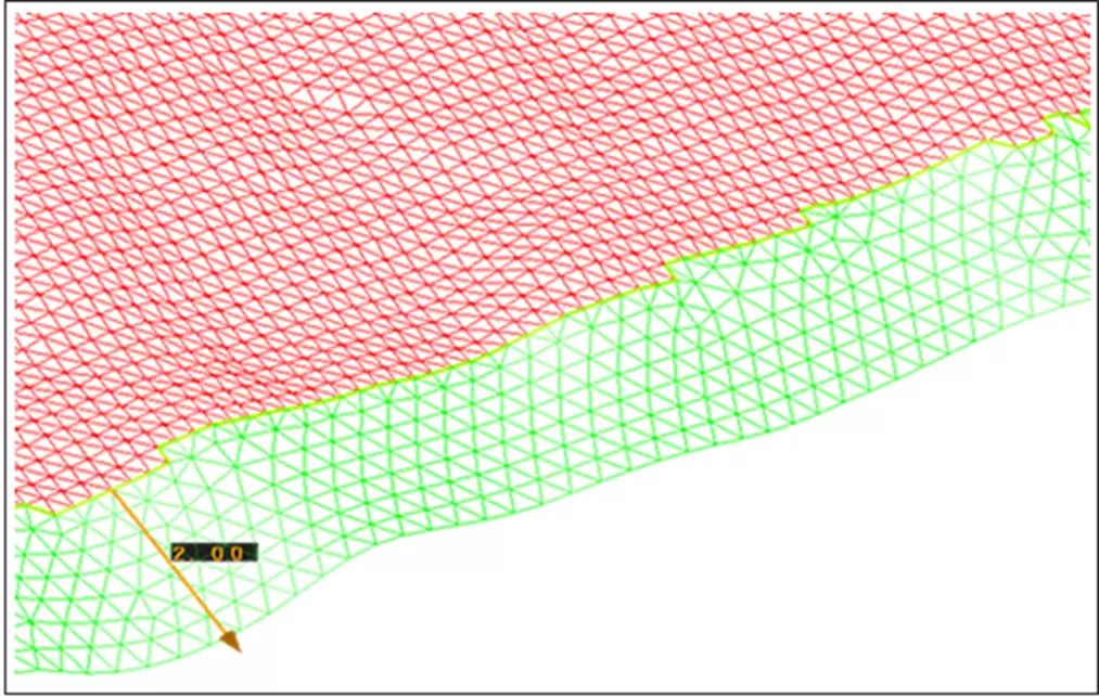
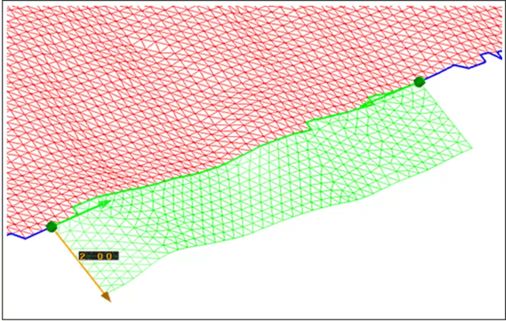
Press Form Twist
Spring back
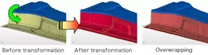
OverCrown

FillingLargeHole
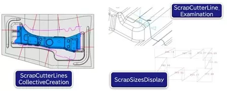
2.3 Mođun DL
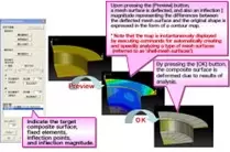
- DL, a 3D support tool, is used to improve product quality and optimize mold layout during the design stage. It allows design engineers to inspect and diagnose results using 3D visualizations and to export 3D result data before precise machining.
- Function: "3DDL Support"
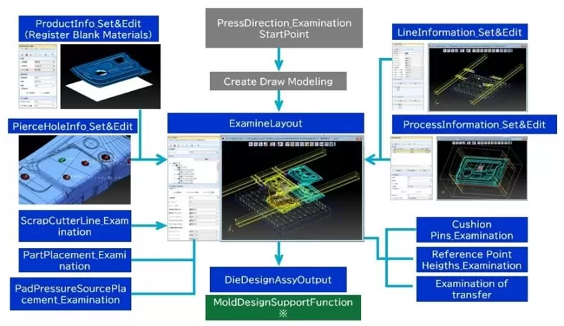
Start point
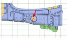
ScrapCutterLineExamination
2.4 Mođun PRESS-FORM-PLUS-II
Related posts

Modern Product Development: Why Many Manufacturers Still Face Product Launch Delays
In today’s manufacturing environment, product development is no longer an isolated task ha...

What Makes New System Vietnam Different in Your Digital Transformation Journey?
As a Gold Partner of Dassault Systèmes, New System Vietnam delivers CAD/CAM/CAE, PLM, cybe...

AI Is Smart, But It's Not Enough: Why Virtual Twin Is Becoming the Foundation of Industrial AI
Discover why Virtual Twin is becoming the foundation of Industrial AI. Learn how connected...

Technology Updates & Trends: How CAD Is Evolving in the Age of AI and Cloud
CAD is no longer just a 3D design tool. Discover how emerging trends such as AI, cloud, an...
CAE in Digital Engineering: When Simulation Becomes More Than Just a Validation Step
Many companies already have CAE in place, yet product development is still not moving fast...