


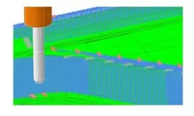
Equal-Height Finishing Machining
3D Integrated CAD/CAM System – CADmeister 2022
CADmeister was first launched by UEL in July 2005 and is the only 3D integrated CAD/CAM system developed in Japan, with more than 30,000 users, mainly mold manufacturing companies. UEL continuously updates market trends and improves the performance of CADmeister. In September 2022, UEL released a new version of its 3D integrated CAD/CAM system, “CADmeister 2022.”
Table of Contents
“In CADmeister 2022, we have upgraded and renewed CAM functions and strengthened other processing capabilities to achieve high-quality and high-efficiency machining in mold manufacturing. In addition, by optimizing 3D design through collaboration with IoT and analysis technologies, and by enhancing integration with downstream processes, the solution contributes to a significant reduction in mold production lead time.”
[Upgraded Features]
The key improvements introduced by UEL in CADmeister 2022 include the following four highlights.
1. Enhanced CAM Functions
High-quality, high-efficiency machining capabilities:
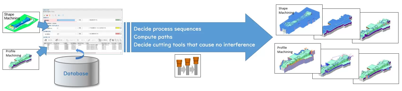
With this new version, the CAMX module has been added to the CADmeister application, equipping the software with full 3D CAM functionalities such as a toolpath calculation engine and path optimization functions. These capabilities are comparable to those of CAM-TOOL, Japan’s leading mold machining software developed by C&G Systems Co., Ltd., a long-term partner of UEL since 2009.
In finishing operations, the NC data configuration point alignment function enables smooth machining and delivers high-precision surface quality.
High-quality and high-efficiency mold machining is achieved through direct cutting of high-hardness materials.
Fast drilling cycle creation without machine operator intervention:
- Added to the “Piercing Die Hole Shape Creation Function (*1)”.
- It is now possible to automate hole machining for piercing dies—tasks that are traditionally performed manually by machine operators—to ensure proper alignment with actual machining conditions (2) at pre-machined positions.
- Hole depth is automatically determined by considering the product surface geometry and the dimensions of the piercing die. The system can also automatically generate extra holes (3) and anti-rotation hole shapes.
- By integrating with CADmeister’s drilling functions, this feature supports full automation of drilling processes for piercing dies while preventing cutting tool collisions during drilling.
3. 3D Design Functions Dedicated to the Mold and Tooling Industry
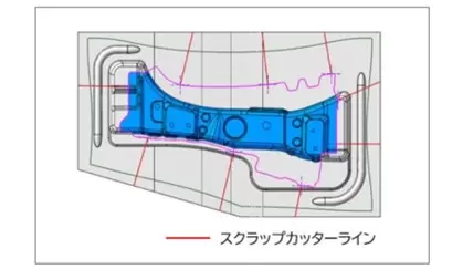
**3DDL (6): Scrap Sheet Cutting Check and Cut-Line Creation (7) (for stamping dies):
This function adds a cutting check capability for excess metal sheets in stamping dies. By inputting conditions such as the maximum allowable scrap size, the system automatically evaluates and generates cut lines, which are then displayed on the part. Design engineers can freely adjust these cut lines based on the visual feedback. This enhancement significantly improves the efficiency of a task that traditionally requires considerable time during die layout design.
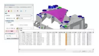
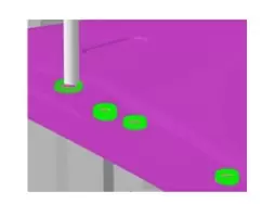
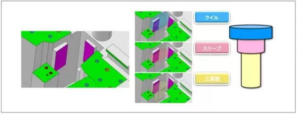
3D Mold Design: Machining Limit Verification Function (for stamping dies):
As a function to enhance collaboration with downstream processes, the Machining Limit Verification function has been added. It allows users to check 3D design data in advance to identify areas that cannot be machined due to potential collisions between cutting tools and part surfaces.
Based on information such as holder size, chuck dimensions, and cutting tool specifications, the function identifies areas where collisions may occur and where machining is not feasible directly from the 3D design data.
This helps reduce machining errors and shorten mold manufacturing lead time.
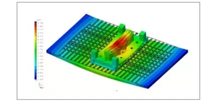
Release of Analysis Functions Dedicated to Plastic Injection Molds:
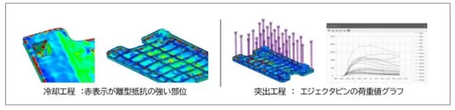
UEL has enhanced and improved capabilities for analyzing the mold separation (demolding) process, as well as enabling prediction and evaluation of causes and countermeasures for mold-related defects—such as deformation, whitening marks, and weld lines—that may occur after plastic parts are ejected from the mold cavity.
The analysis focuses on the cooling phase only, specifically between the cooling process / mold opening process / ejection (injection molding) process.
- Undercut profile verification
- Plastic material specification
With these capabilities, the causes and countermeasures for parts sticking to the *cavity surface (8) can be analyzed more accurately and in a shorter time. In addition, the balance of *ejector pin (9) placement at areas with strong demolding resistance on the *core side (8) can be evaluated more precisely and efficiently.
4. Improved Visual Operation and Enhanced Visibility
By analyzing customer workflows from multiple perspectives, we have achieved more intuitive operation and improved the visibility of 3D models. This provides a user-friendly and comfortable working environment for CAD/CAM engineers.
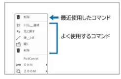
- Drawing command selection has been simplified and accelerated.
- “Recently Used Commands” and “Frequently Used Commands” have been added to the pop-up menu, enabling engineers to select desired commands more easily.
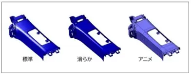
*Enhanced Shading Display (10)
Shading display options have been enhanced with the addition of “Smooth” and “Animation” modes, offering various lighting methods and brightness levels. In addition, a “Material” display option has been introduced, allowing parts to be switched to material-based visualization with a single simple operation.
With the CADmeister 2022 version, including both existing customers and those who have introduced CADmeister to others, UEL expects that by the end of 2023, CADmeister will have sold approximately 5,300 licenses.
Notes in the article:
*(1): Piercing hole
One of the structures used to punch holes in sheet material using a stamping die. It is the receiving part used during punching to fit into the lower die plate.
*(2): Fit to actual conditions
In machining, when dimensions are not specified on drawings, additional features are fabricated based on existing workshop conditions using methods such as punching, welding, or bending so that parts can be assembled together. This is also referred to as gengo.
*(3): Scrap hole
A hole used to drop scrap material that is punched out by a piercing die during press operations.
*(4): One stroke
A single press cycle in which pressure increases from the top dead
Related posts
Modern Product Development: Why Many Manufacturers Still Face Product Launch Delays
In today’s manufacturing environment, product development is no longer an isolated task ha...

AI Is Smart, But It's Not Enough: Why Virtual Twin Is Becoming the Foundation of Industrial AI
Discover why Virtual Twin is becoming the foundation of Industrial AI. Learn how connected...

Technology Updates & Trends: How CAD Is Evolving in the Age of AI and Cloud
CAD is no longer just a 3D design tool. Discover how emerging trends such as AI, cloud, an...
3DEXPERIENCE Customization: Tailoring the System to Fit Your Business Processes
Customize 3DEXPERIENCE to fit your business processes with NSV’s 3DEXPERIENCE Customizatio...

Understanding CAD in Enterprises: From Design to Data and Manufacturing
In many engineering organizations, CAD is still viewed primarily as a drafting tool used e...