


Accelerate Mold Machining Performance with CAM-TOOL V20.1 – Part 2: Toolpath Upgrades and Enhancements
The new cutting mode, “Adaptive Roughing,” enables climb milling while maintaining a constant cutting force during machining. This is achieved by independently controlling (slowing down) the spindle speed in the XY direction.
1. New Machining Strategy: Adaptive Roughing
The new cutting mode, “Adaptive Roughing,” performs climb milling while maintaining a constant cutting force throughout the machining process. This is achieved by independently controlling (slowing down) the spindle speed in the XY direction.
⇒ As a result, cutting forces are effectively controlled, tool wear is reduced, and more efficient toolpaths are generated—minimizing unnecessary tool retractions when machining island features.
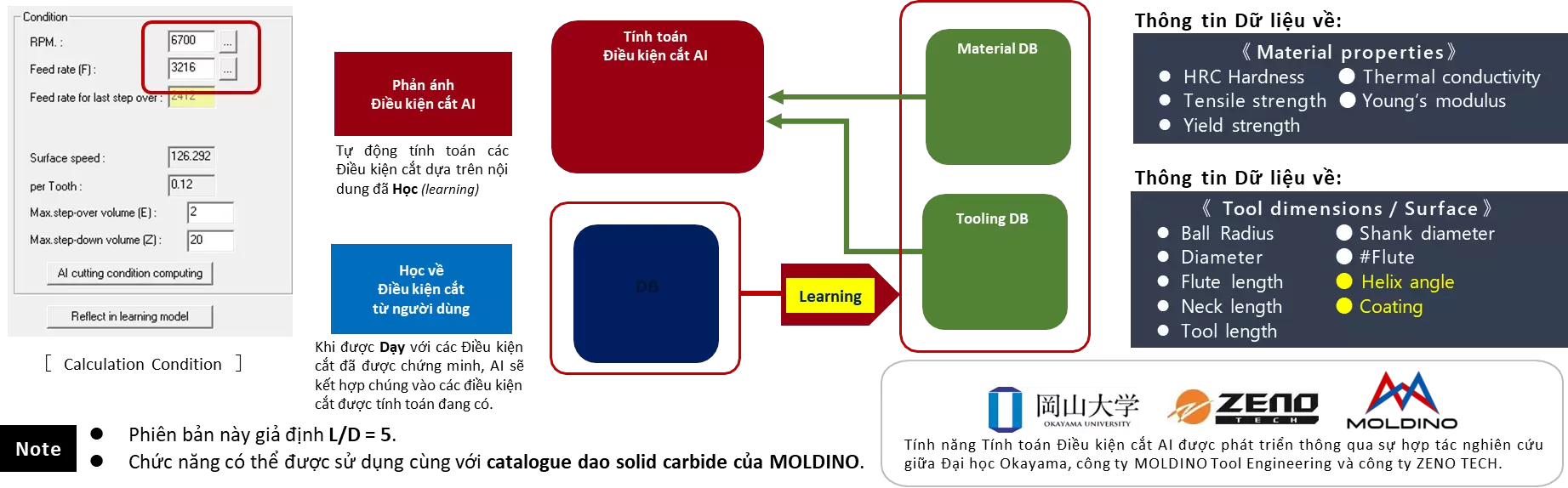
2. AI-Based Cutting Condition Calculation
By leveraging a “Data Mining Methodology” powered by Artificial Intelligence, cutting conditions can be calculated automatically and accurately.
⇒ This approach addresses challenges such as programming across multiple material types, working with end mills that CAM engineers may have limited machining experience with, or reviewing existing cutting conditions to improve programming and machining efficiency. Furthermore, by learning from proven cutting conditions, AI enables users to build a proprietary machining knowledge database—unique to each department and organization.
☼ What is the “Data Mining Methodology”?
Data mining methodologies apply statistical analysis techniques and advanced artificial intelligence technologies to discover valuable patterns and rules from large volumes of data stored in databases.
3. Z-Level Finishing (Polygon)
Defining Toolpath Output Using the Division Angle
It is now possible to output Z-level toolpaths that exceed the specified Division Angle. When Low-Lying Area Cutting is set to OFF, toolpaths below the defined angle are considered low-lying areas; therefore, the system skips generating toolpaths that are deemed unsuitable.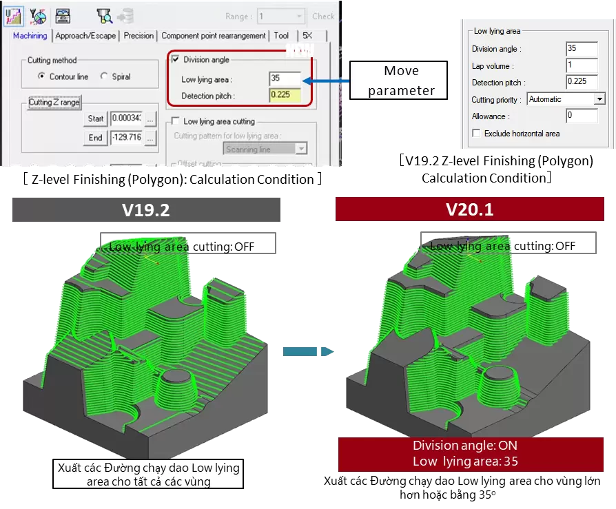
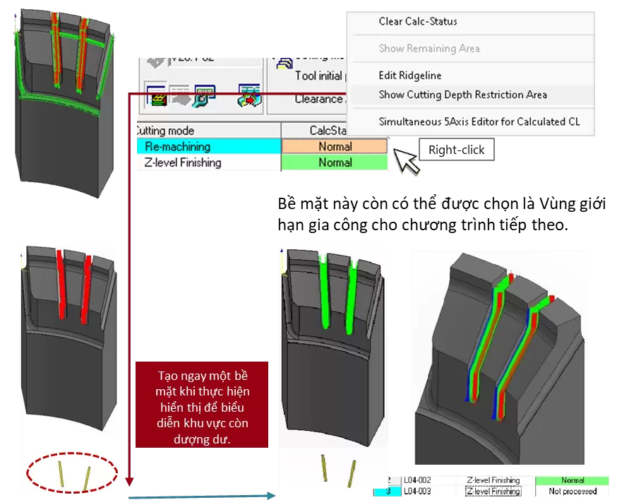
4. Re-Machining
Show Cutting Depth Restriction Area
This function creates a surface representing the remaining stock in areas constrained by the Cutting Depth Restriction Area. This surface can then be assigned as the machining area in subsequent operations, reducing manual steps and the time required to define machining restriction zones.
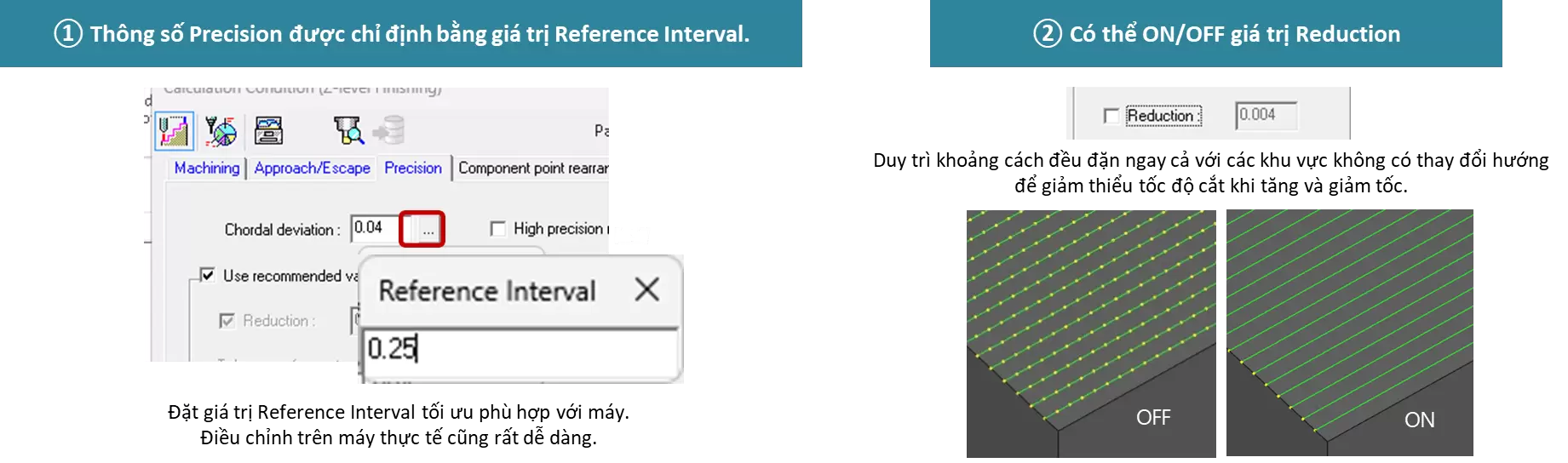
5. 3D Machining Strategy-1: GUI Settings in the Precision Tab
A new environment has been developed to specify the G01 segment length (Reference Interval) within the 3D-1 machining strategies.
⇒ This helps eliminate tool marks on machined surfaces caused by acceleration and deceleration of the machining center, thereby supporting high-quality machining results.
(*The Curve Control Along Surface strategy has not yet been developed.)
① Chordal deviation calculation based on the specified Reference Interval value has now been added.
② A “Reduction” ON/OFF parameter has been introduced to maintain consistent Reference Interval spacing in flat areas and similar regions.
6. 3D Machining Strategy-1: Use Recommended Value (RV) Parameter
③ The curve tolerance (accuracy) for curvature profiles has been renamed to “Minimum Interval”, replacing the previous Tolerance parameter.
④ The Recommended Value (RV) calculation method has been revised to meet higher requirements for accuracy and surface quality.

7. Divide CL: Equal Division Function
The Equal Division function has now been added to the Divide CL command.
The system automatically adjusts the process to divide it evenly based on either Cutting Distance or Cutting Time.
⇒ This enables more accurate time estimation, allowing engineers to monitor operations and change tools based on tool wear, thereby preventing product defects during machining.

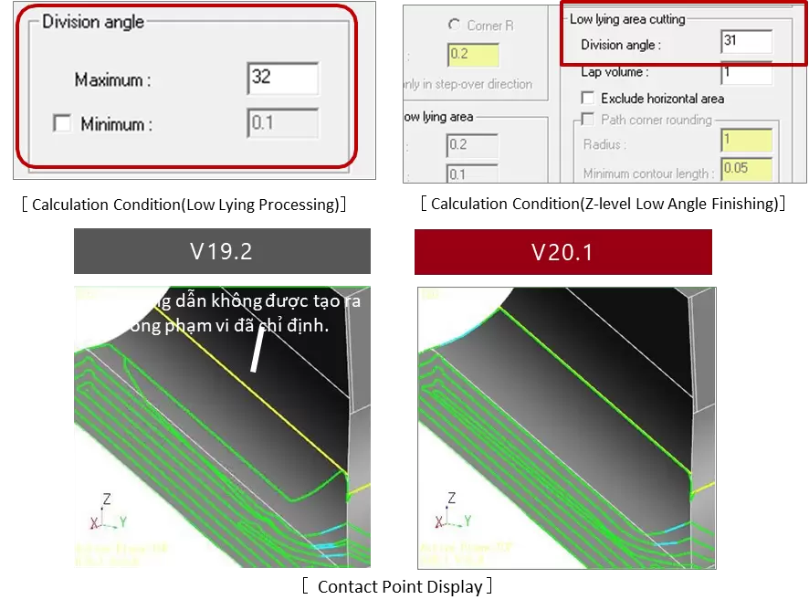
8. “Wall” Feature in Low-Lying Processing and Z-Level Low Angle Finishing
Improved accuracy in recognizing vertical walls using the Division Angle parameter. This enhancement enables the generation of smoother toolpaths for effective remaining material removal and reduces toolpath oscillations that occur when machining areas include transitional profiles such as fillet regions.
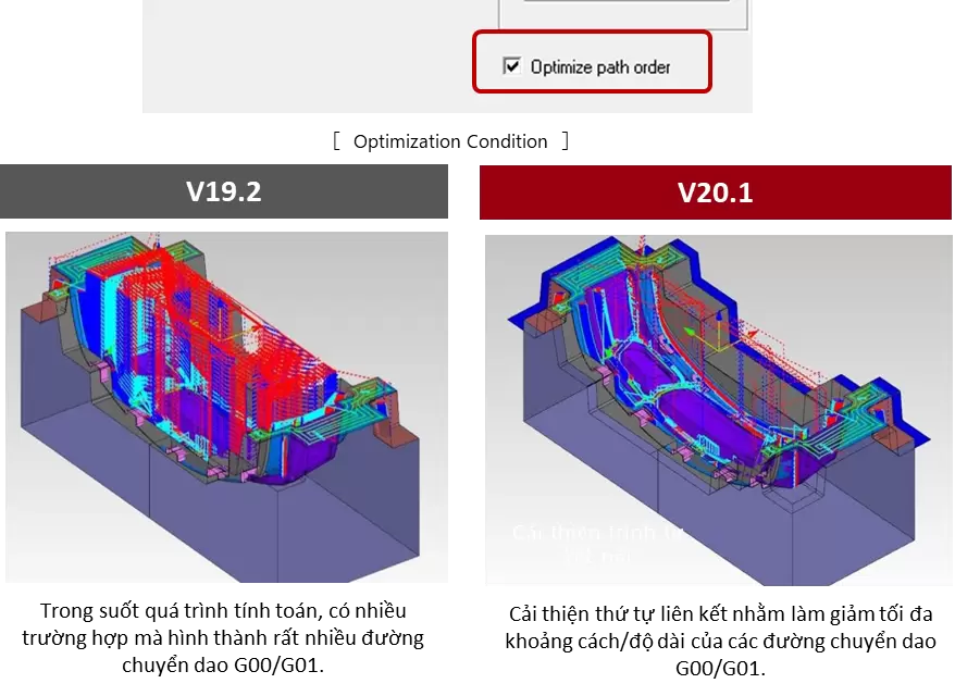
9. Z-Level Rough Cutting with Multiple Tools: Optimize Cutting Order Feature Added
Advancements in sequential connection logic significantly reduce long-distance G00/G01 tool movements during stock calculation, optimizing retract motions and substantially shortening machining time.
In addition, relaxed restrictions on simultaneous use with other functions broaden the range of applicable machining scenarios.
10. Stock Calculation: Expanded to Additional Machining Strategies
Stock Calculation automatically detects remaining machining stock by comparing the Product Shape with the Stock Shape, and generates toolpaths for unmachined areas.
⇒ This function has now been expanded to cover existing finishing strategies, significantly reducing the workload required to define machining support areas.

11. Separate XY/Z Stock Allowance: Integration for Special Tools
When using a Special Tool Created, machining stock allowance can now be controlled separately in the radial (XY) and axial (Z) directions.
⇒ This is particularly effective for rough machining of large mold components, where a certain finishing allowance is required on wall profiles, while only additional machining on bottom surfaces is needed to achieve final accuracy and surface finish.

12. Combined Enhancements Using Face Not to Machine and Fillet Features
The cutting mode has been expanded to allow simultaneous use of Face Not to Machine and Fillet features. By applying fillets to machined profiles other than the Face Not to Machine surface, two-point tool contact is prevented, resulting in more stable and reliable machining.

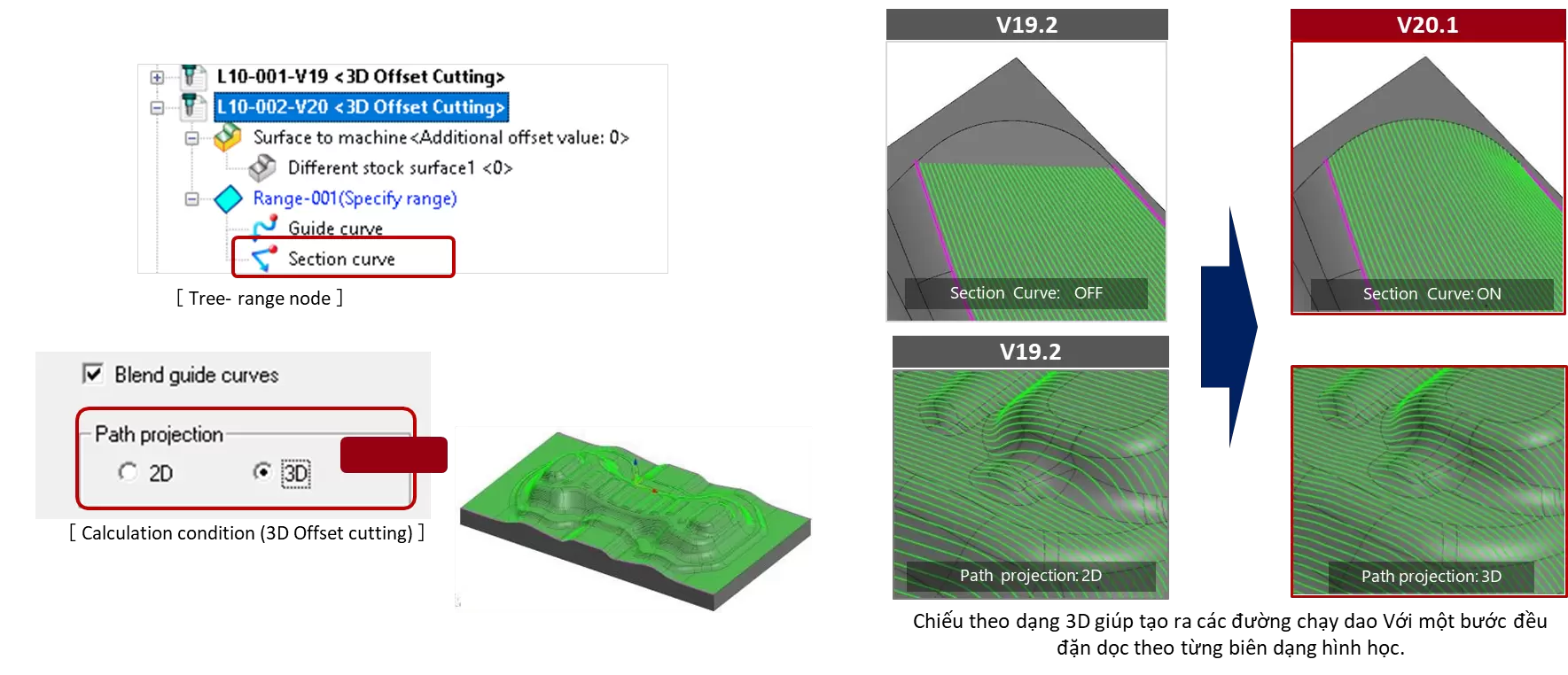
13. 3D Offset Cutting: Section Curve Feature Added
A Section Curve range setting has been added. By defining the machining area based on the lateral tool offset direction, toolpaths are generated for the entire specified region.
In addition, the Blend Guide Curve command allows users to select the projection method for toolpaths, enabling the generation of tool guidance that better matches geometric characteristics.
Related posts

How to Shorten Product Development Time: 5 Critical Factors Companies Often Overlook

Modern Product Development: Why Many Manufacturers Still Face Product Launch Delays
3 Enhancements in CAM-TOOL V21.1 That Improve NC Programming Efficiency and Mold Machining Performance

CAM-TOOL / CADmeister / Excess Hybrid – Software Solutions for the Machining Industry
